Uncategorized


Constant Monitor Selection Guide: Impedance Vs. Resistance

August 22, 2015

Download our slide show here: CM2800 Constant Monitor Capabilities 

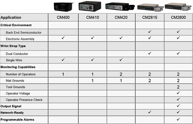
ESD Constant monitors reduce production costs by eliminating the time spent on testing wrist straps before each shift. Further savings may be realized by reduced ESD damage from broken wrist straps. Transforming Technologies manufactures two types of monitors:

Impedance (or single wire) constant monitors

The impedance monitor uses a detection circuit designed to reduce false alarms and eliminate adjustments. It uses the phase difference between current and voltage to detect changes in impedance of the cord, band and person. A very low AC voltage is used for constant sensing. Any standard wristband and coil cord can be used.

Resistance (or Dual Wire) constant monitors

This type of monitor is used with a two wire (dual conductor) wrist strap. When a person is wearing a wrist strap, the monitor observes the resistance of the loop, consisting of a wire, a person, a wrist-band, and a second wire. If any part of the loop should open (become disconnected or have out of limit resistance), the circuit will go into the alarm state. An important feature of the Dual Wire Wrist Strap is that even if one conductor is severed, the operator has reliable path-to-ground with other

Transforming Technologies Line of Constant Monitors.
Click here for more information.

monitor-selection-guide


Dual Conductor Grounding is Dependable, Convenient, and Accurate!

July 12, 2015


Transforming Technologies, proudly introduces, our new line of dual conductor coil cords, wrist straps and our exceptional resistance workstation monitor, the CM2015.

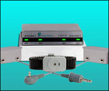
Dual conductor resistance workstation monitoring is the most reliable grounding system available. Resistance monitors use specialized wrist bands and ground cords which contain two independent conducting elements that provide fail-safe ground protection. The CM2015 uses only 200mv and continuously monitors two (2) operators and two (2) work surfaces

Designed to compare with 3M* dual conductor wrist straps, Transforming Technologies now offers a value alternative for these premium products. We incorporate the best design elements of expired patent # 5,018,044 with our own experience making premium quality ESD products. Transforming Technologies and 3M’s dual conductor products are functionally equivalent. The wristbands, coil cords and resistance monitors can be use together in any combination!

Download our Dual Conductor Brochure

Resistance Workstation Monitor 

cm2015-kit-2Utilizing very precise, low voltage, resistive loop technology, the CM2015 is an extremely sensitive and reliable instrument that uses the operator’s skin resistance to determine if the system is operating properly.

Audible and visible alarms are triggered if the operator’s resistance exceeds 10 or 35 megohm (electable at factory with default of 35 megohm). Low resistance   also triggers an alarm event.                                                       CM2015                                                                                                                                                            Used with Dual Conductor Wrist Band and Coil Cords

Dual Conductor Wrist Bands

WB0070 (Fabric) /WB0050 (Metal)                                                                                                                                                                                     
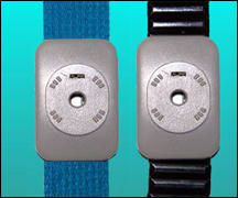
Dual-wrist-bandDual Conductor wrist strap sets are used to maximize ESD protection. These specialized bands use two contact circuits to create a two paths two ground.

  • WB0050: An expandable Speidel®* metal band available in small, medium and large sizes.
  •  WB0070: One-size-fits-all! Features a silver-plated, monofilament, continuous                                                           thread with elastic nylon for full                                                                         conductivity and comfort.

Dual Conductor Coil Cords

CC3000 Series Dual-Coil-COrd

Transforming Technologies Dual Conductor Coil Cords provide unmatched reliability and value. The CC3000 features a double insulated jacket that provides incredible durability.

A wide diameter straight plug makes it easy to insert and remove the cord from a remote input jack. The CC2080 series features dual grey and black 4mm sockets                                                            help maintain a constant connection.

Our Mission

Transforming Technologies’ mission is to provide you with the highest quality ESD products in the industry. We continuously research and develop new technology in static control so that we can provide you the best products possible. Our name is not a coincidence, it is our goal to transform the ESD industry and we do that one new and unique product at a time.

Transforming Technologies has the ESD protection you need.

Contact us today.


New Product Announcement: TileSTAT Interlocking Anti-Fatigue ESD Tiles

February 25, 2015

Transforming Technologies is proud to announce the addition of the TileSTAT Interlocking Anti-Fatigue ESD Tiles to our line of ESD products.

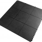
TileSTAT Interlocking ESD Rubber Anti-FatigueTiles

TileSTAT Interlocking ESD Rubber Anti-FatigueTiles

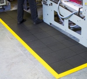
TileSTAT Interlocking Rubber Anti-Fatigue ESD Tiles are a heavy duty, durable safety mat constructed of conductive nitrile rubber for use in even the harshest environments. TileSTAT mats feature a solid pebble embossed surface for improved traction, making this a good choice as a safety mat. The 3ft x 3ft interlocking mats fit together like a puzzle to create custom ESD workstations or complete room systems. The mats can be quickly dismantled to make moving and cleaning easy. Optional beveled borders can be added to the mats.


Meets or exceeds requirements of ANSI ESD-S20.20 and the recommendations of ESD STM7.1

Benefits & Features of the Transforming Technologies TileSTAT Anti-Fatigue ESD Tiles:

  • 100% conductive rubber: 10^4-10^6
  • Solid top design for use in wet or dry locations
  • Interlocking sections snap together to easily create custom workstations
  • Optional yellow beveled borders for safety

Specifications of the Transforming Technologies conductive TileSTAT Anti-Fatigue ESD Tiles:

  • Point-to-point resistance: 10^4-10^6
  • Surface: Solid Top Pebble Emboss
  • Meets or exceeds requirements of ANSI ESD-S20.20 and the recommendations of ESD STM7.
TileSTAT Interlocking Anti-Fatigue ESD Tiles

TileSTAT Interlocking Anti-Fatigue ESD Tiles

TileSTAT Interlocking Anti-Fatigue ESD Tiles (Underside)

TileSTAT Interlocking Anti-Fatigue ESD Tiles (Underside)

TileSTAT Interlocking Anti-Fatigue ESD Tiles w/ Yellow Beveled Edges

TileSTAT Interlocking Anti-Fatigue ESD Tiles w/ Yellow Beveled Edges


For price and availability on the TileSTAT Interlocking Anti-Fatigue Tiles or for information on any products in Transforming Technologies full line of ESD products, please call 419-841-9552 or email info@transforming-technologies.com.


Basic Troubleshooting for the BFN Ionizers

October 16, 2014

Limited Warranty for our Ionizers and Test Equipment

Transforming Technologies expressly warrants that for a period of one (1) year from the date of purchase, Transforming Technologies ESD products will be free of defects in material (parts) and workmanship (labor). Within the warranty period, a unit will be tested, repaired or replaced at Transforming Technologies option, without charge. Call our Customer Service Department for a Return Material Authorization (RMA) and proper shipping instructions and address.

Our Mission

Transforming Technologies’ mission is to provide you with the highest quality ESD products in the industry. Occasionaly problems arise this We continuously research and develop new technology in static control so that we can provide you the best products possible. Our name is not a coincidence, it is our goal to transform the ESD industry and we do that one new and unique product at a time.


Generating Air Ionization With No Contaminating Particles

May 6, 2014

Abstract

High Technology manufacturing employs air ionizers to reduce the effects of static charge. In cleanrooms the dominant issue is contamination reduction by eliminating electrostatic attraction. Conventionally, air ionization is generated by corona from needle electrodes, but there are particles generated by this process and removing the debris collected on the needle electrodes represents a significant maintenance issue. In the past, particles generated by ionizers have been too small to affect the manufacturing process, but this is no longer true. The latest small structures on the wafer have reached the limit where these particles will harm the product. This paper discusses the mechanism for particle creation and presents a design which creates no particles. The maintenance issue has lead to the use of complex ionizers that employ a sheath of air to shield the corona electrodes from the air in the cleanroom and the associated airborne molecular contaminants (AMCs). The new technology which eliminates particle generation also eliminates the need to clean the ionizers and reduces or eliminates the amount of air required to operate the ionizer.

For the full text click here.


Heel Grounders:One Meg Resistor vs. Two Meg Resistor

February 25, 2013

Heel Grounders and ESD Protection

Heel grounders discharge static from a person to ground by connecting the person to a grounded walking surface. A conductive ribbon placed inside the wearer’s shoe or sock makes electrical contact with the skin through perspiration. The ribbon is joined to a resistor which limits current should acci-dental exposure to electricity occur. The other end of the resistor is joined to a conductive sole. This sole contacts a grounded ESD floor mat or ESD flooring system. Heel grounders should be worn on both feet to maintain ground contact while walking. UL and OSHA recommends a minimum of 1 megohm resistance to ground (RTG) in order to limit current for safety purposes.

Resistors and Heel Grounders

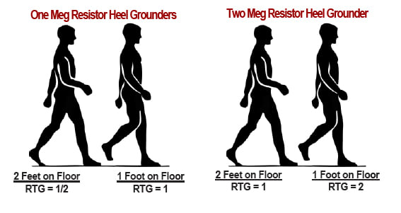
Heel grounders come with either a 1 megohm or 2 megohm resistor. When one foot is on the ground, a 1 megohm heel grounder gives you an RTG of 1 megohm and a 2 megohm heel grounders results in 2 megohm RTG. But when both feet are on the ground, the sum of the resistors yield a RTG of 1/2 that measurement.

For example:

  • When you wear two, 1 megohm heel grounders and have both feet on the floor, your RTG is only 1/2 megohm, NOT 1 megohm!
  • If you wear two, 2 megohm heel grounders an have both feet on the ground, your RTG is 1 megohm.
  • By wearing two heel grounders with a 2 megohm resistor you are com-plying with UL and OSHA at all times.

one-meg-vs-two-meg-resistor (1)

What is a Resistor?

A resistor is a component of an electrical circuit that resists the flow of electrical current. A resis-tor has two terminals across which electricity must pass, and is designed to drop the voltage of the current as it flows from one terminal to the next. A resistor is primarily used to create and maintain a known safe current.

resistor

Most grounding products have a current limiting resistor and it is most commonly one megohm, rated at least 1/4 watt with a working voltage rating of 250 volts. This ensures that the flowing current will be within safe levels.

Types of Heel Grounders?

Heel Grounders come in a variety of styles:

Cup Style

Made with two reversi-ble soles for longer life span.

Foot Grounder

Provides a more complete path-to-ground due to wider contact area and heel-to-toe coverage.

Disposable

Strip of conductive material is applied to shoe. Economical and perfect for one time use.

Toe Grounder

Ideal for high heels when stan-dard heel grounders won’t fit properly.


CM2800 Constant Monitor Capabilities

September 30, 2012


How EMI from ESD can Affect Your Automation Systems

February 19, 2012

Introduction

When a tool or tester on your line stops working, everyone scrambles to correct it. Such process halts slow the manufacturing process, and cause lower product throughput. Achieving the best equipment up time is a key element in achieving profitability in any automated factory.

When tool halts are random they are quite difficult to troubleshoot. Their frequency could be every few minutes or just once a month!. Equipment diagnostics often provide no information as to the cause of these random equipment problems.

Finding the Cause of the Problem

When an automated process halts sporadically, both the hardware and the software are suspect.  Often there are lengthy finger pointing discussions between the hardware and software engineers which does not bring the problem any closer to a solution.

In some cases, the problem is neither the hardware nor the software.  Rather it can be electromagnetic interference (EMI) generated by electrostatic discharge (ESD). The EMI generated by ESD can exceed immunity levels of automation equipment. ESD discharges occur so fast (typically in nanoseconds) that they radiate EMI extremely efficiently.  This very short transient EMI is surprisingly high in amplitude because all of its energy is packed into a few nanoseconds.  Further, these short EMI transients are not detected by spectrum analyzers.

An electrostatic discharge occurs when charged objects come close enough to ground to cause a breakdown of the air gap between the object  and ground. Transferring wafers or reticles with a grounded robot or plugging a charged IC into a socket are obvious examples of such ESD events. ESD is well-known to cause damage directly to reticles, wafers and ICs.

Once an ESD event injects an EMI transient into a tool, it is efficiently transmitted through the electronic circuitry within the tool.  Circuit boards are laid out to distribute high speed clock signals and thus EMI transients are also transmitted efficiently.   It is important to realize that for EMI to cause an error it must be induced in the circuitry simultaneously with a critical circuit operation.  Thus, many EMI events can occur before one causes a tool error to occur.  This is also the reason that this type of tool halt is random in nature.

The tool halt, may be accompanied by a difficult-to-interpret error message. Equipment diagnostics succeed in making the problem look like a software bug, certainly not  EMI from an ESD event.

Conducted vs. Radiated EMI

When an ESD event occurs, the rapid transfer of charge results in currents that may be hundreds of Amperes. The entire discharge typically occurs in a time interval measured in nanoseconds. While some of the energy is dissipated in heat (which damages silicon and metallization), a significant portion of the energy becomes electromagnetic radiation. This generally occurs in the 25 MHz to 2 GHz frequency range. It may be conducted away from the site of the ESD event through a metal structure or a power line, or it may radiate through the air. In either case it may affect equipment at a considerable distance from the location of the ESD event.

Identifying ESD caused EMI

ESD diagnostics are not part of the toolkit of most production engineers. As an illustration, a manufacturer of microprocessors was experiencing random equipment problems with one of nine steppers in the photolithography area. In-house engineers and the equipment manufacturer’s field service engineers tried software upgrades and replacement of major stepper components. After 6 months of frustrating and unsuccessful investigation, a well known  ESD consultant made measurements with an antenna and a wide band digitizing oscilloscope.  He detected a random signal on the power supply line of the stepper occurring about once a minute. The random nature of the signal pointed to EMI as the possible cause of the problem.

An electrostatic field-meter found static charge developing on a panel and identified the cause of the problem in less than one hour. One of the wall panels above the stepper was not connected to ground. This large isolated conductor was becoming charged, and then discharging to the nearby grounded wall framing. The EMI from the ESD event was causing the equipment interrupts.

Diagnostic Clues

When an unexplained phenomenon occurs in a random fashion on some tools of a given tool type but not all of them that is a clue.  When a “software bug” is evident on some tools but not all but the tools have the same Rev Level of software, that is another clue.  Most importantly, do not wait six months before considering this cause for the problem.  There are tools for the detection of these transients that range from multi Giga Hertz digitizing oscilloscopes to simple EMI locators designed to be sensitive to these transients.

Conclusions

Many equipment failures are the result of random ESD events and a great deal of production and engineering time is wasted pursuing phantom software problems.

Charge generation is unavoidable in many high tech manufacturing processes due to the presence of easily charged insulating materials. It is impossible to assure that everything is continuously connected to ground and that ESD events will not occur. 5 Making ESD control part of your arsenal of tools to keep your factory running smoothly is an important addition.

LBL Scientific 

References

1. Levit, L., Menear, J.”Measuring and Quantifying Static Charge in Cleanrooms and Process Tools”, Solid State Technology, February 1998. PennWell.

2. Honda, M., et al, “Method of Observing ESD Around Electronic Equipment”, ESD Symposium, September 1996, ESD Association, 7900 Turin Road, Rome NY 13440.

3. Peters, L., “ESD Can Be a Tool’s Worst Enemy”, Semiconductor International, September 1997, Cahners Publishing Company.

4. SEMI E78-0998 “Guide to Assess and Control Electrostatic Discharge (ESD) and Electrostatic Attraction (ESA) for Equipment, September 1998, SEMI.

5. Galatowitsch, S., “Terminating Static in the Cleanroom”, Cleanrooms, April 1998, PennWell.
 

Electro Static Discharge Basics

January 8, 2012


ESD Portable Field Service Kits: Procedure and Care

November 5, 2011

ESD Protection in the Fieldesd-field-service-kits-mats-sp

Static damage is a constant threat anywhere micro-electronic com-ponents are used, but these components are at highest risk during servicing. The Transforming Technologies’ FSM2424 Field Service Kit is designed to quickly and reliably remove static charge on the service technician and provide a safe static-free surface to lay parts. The kit includes a 24” x 24” rugged mat with two 8” x 12” pockets for storing tools, an adjustable wrist band, coil cord and 15’ ground cord.

The FSM2424 Field Service Kits eliminates static charge through the principle of grounding. Both the mat and the operator’s wrist band connect to the specialized ground cord which when properly connected to ground, provides a safe path for static charges to drain to ground.

Field Service Procedure

  1. Upon arrival at the service call site, unpack the field service kit in a convenient area near the equipment to be serviced.
  2. Remove any accessories from the pockets and attach the ground cord to the mat via one of the two snaps found in the corner of the mat.
  3. Connect the opposite end of the cord to a reliable ground. Common ground locations are water pipes, unpainted equipment frames, and building frames.
  4. Slip on the wrist band and adjust the size to fit comfortably around the wrist but tight enough to make contact with the skin at all times. Snap the coil cord to the wrist band.
  5. Insert the banana plug of the coil cord into the jack of the ground cord. This connects the wrist band to the same common ground as the work surface.
  6. It is now safe to remove and handle static-sensitive components.

Field Service Care

The FSM2424 Field Service Kits can be cleaned with ESD-safe mat and surface cleaner or with a mild detergent and water as needed. Once clean, allow the material to air dry, removing any excess water/moisture with an absorbent cloth. DO NOT use heat of any kind to dry mat. Though inherently flame resistant, the field service products will burn with enough exposure to open flame or other heat sources of sufficient temperature. DO NOT use a clothes dryer, as the excess heat may cause the PVC material to retain the shape it held in the dryer. Most strong solvents are not recommended. AVOID: Halogens, concentrated Oxidizing Agents, Ethers, ketones, and Low-Molecular Weight Solvents derived from the Ether and ketones fami-lies. They include (but are not limited to) TetraHydroFuran (THF), Methyl Ethyl ketone (MEK), Methyl Isobutyl Ketone (MIBK) and Acetone. These chemicals will mar and/or destroy the sur-face of the PVC product (the Ketones), react with it (Oxidizing Agents), or actually dissolve it (THF and other Ethers). Wrist strap can be hand or machined washed.


Translate »